
|
|
|
|
Ekco Radio Continued,
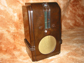
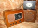
Model AC97 Shown above is a picture of the AC97 from 1936.
This receiver was housed in one of the most stunning of all the Ekco
bakelite cabinets. The cabinet was
designed by Jesse Collins, and is the tallest radio, (at 21 high), housed in
a bakelite cabinet that I know of. The cabinet is quite susceptible to damage because of its
size and the large continuous areas of flat un-contoured bakelite.
The cloth covering the 9 speaker, unlike previous Ekco receivers, is
completely unprotected by bars or
mouldings, hence the cloth is more
often than not found to be damaged or a replacement.
Fortunately the cabinet and cloth on my receiver are both in good
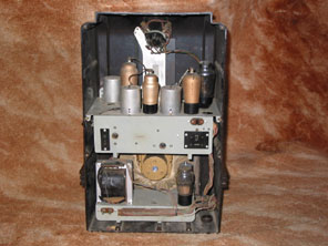
original condition. Like the ACT96
on the previous page, the AC97 has its power supply section on a different
chassis to the main radio chassis. The
power supply including the mains transformer, smoothing capacitors and rectifier
is mounted at the base of the cabinet, and is connected to the upper chassis by
an eleven way cable. The circuit of
the AC97 was designed to produce a high quality sound, and this was the first
and only Ekco receiver to include a fidelity control. The fidelity control was basically a three position switch
mounted at the front right of the cabinet.. Ganged
together with the fidelity switch are the further contacts that
decrease the upper frequency response of the receiver.
Also provided for the first time was a mystic eye.
This was Ekcos term for the more commonly known magic eye, a
cathode-ray display that indicated when a station was accurately tuned-in.
Unlike most manufacturers though the mystic eye was not discretely and
unobtrusively placed within the tuning scale area, but right above the tuning
column at the top of the cabinet, so that the green glow is visible from the top
and front of the receiver. When the
receiver is operated in a room with subdued lighting the effect is quite
stunning, with a vertical column of light from the tuning scale, crowned with
the mystic eye and its phosphorescent green aura. The cabinet itself is a monument to Art Deco design, and
the similarity of the stepped sides at the top are apparent when compared
to buildings built in the 1930s, such as the Crysler Building in New York for
instance. You might also just be able to see that the knobs are octagonal,
rather than the more usual round shape. Also notable of the AC97 is the output valve which utilises
a 2v heater. As the rest of the
receiver is using fairly ubiquitous 4v heaters
the result is that the output valve cannot be placed in the normal heater chain. Instead the output valve is provided with its own 2v winding
from the mains transformer. When
you consider that as well as the 2v O/P valve heater tapping, the 4v general
heater tapping, the independent 5v rectifier tapping, and the HT tapping are all
required to be supplied from the mains transformer, it is something of a problem
if the mains transformer fails, as scavenging another from a scrap receiver is
not so straightforward. In fact
when I first obtained my example, the mains transformer had obviously failed
(decades ago), and a more common transformer without the separate 2v tapping had
been used in its place. This meant
that an output valve with a 4v heater had been substituted.
Fortunately I was able to find a genuine spare salvage Ekco transformer,
and the output stage has been converted back to original.
It has been suggested that Ekco used an output valve with a 2v heater
because the noise level caused would be lower than that from a 4v heater.
As much effort has been taken elsewhere in the receiver to eliminate
noise (for example by the whistle rejector circuits) then this would seem
likely. Certainly it would have
been easier for Ekco to solely use 4v heater chain and output valve such as an
ACO44 or PX4 etc. The AC97 valve
line-up is FC4, VP4B, TDD4, ACO42, IW4/350, TV4. The receiver cost £13.2.6 and a black and white version
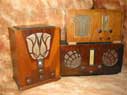
was also available (the tuning scale surround and knobs were white). Continue for the wooden cabinet of the Ekco
AW108 © COPYRIGHT RETAINED ON ALL TEXT AND PICTURES ON THIS SITE.
|